PoE (Power Over Ethernet) refers to some IP-based terminals (such as IP power, wireless LAN access point AP, network) without any changes to the existing Ethernet Cat.5 cabling infrastructure. Cameras, etc., while transmitting data, can also provide DC power supply technology for such devices. PoE technology can ensure the normal operation of existing networks while minimizing costs while ensuring the security of existing structured cabling.
A complete PoE system consists of two parts: the power supply device and the power receiving device.
Power Supply Equipment (PSE): An Ethernet switch, router, hub, or other network switching device that supports POE.
Receiving device (PD): In the monitoring system, it is mainly the network camera (IPC).
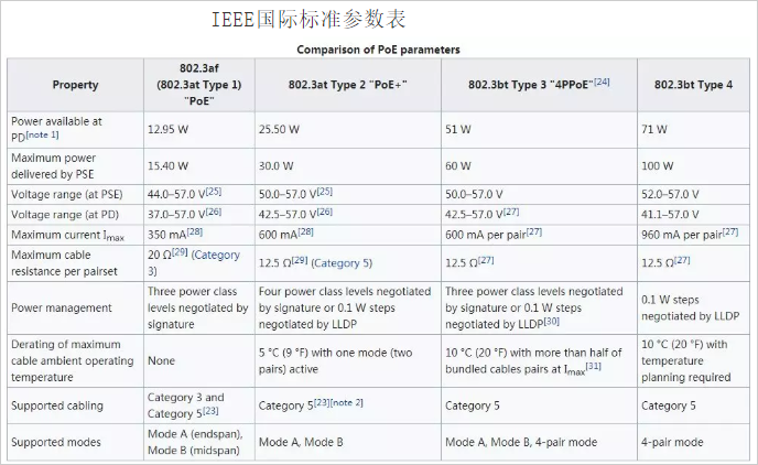
The IEEE802.3af, an international standard established in 2003, requires PSE to achieve an output power of 15.4W, while the power reaching the powered device is 12.95W and the power loss is 2.45W. The IEEE802.3at, an international standard established in 2009, requires PSE to achieve an output power of 30 W. The power reaching the powered device is 25.5 W and the power loss is 4.5 W. Over time, the power of these two standards has been unable to meet the power requirements of the new, more powerful PDs. Therefore, the new international standard IEEE802.3bt has two requirements, one of which is that the PSE can achieve 60W output power, the power reaching the powered device is 51W, and the power loss is 9W. The other requires the PSE to achieve 100W of output power, the power to the powered device is 71W, and the power loss is 29W.
It can be known from the above standards that as the power supply increases, the power loss is not proportional to the power supply, but the loss is getting larger and larger. So how can the loss of PSE in practical applications be calculated?
Then let us first look at how the loss of wire power in junior high school physics is calculated.
Joule's law is a law that quantifies the conduction current to convert electrical energy into heat. The content is: the heat generated by the current through the conductor is proportional to the square of the current, proportional to the resistance of the conductor, and proportional to the time of energization. Joule's law mathematical expression: Q = I2Rt (applicable to all circuits) where Q is the power P of the loss, I is the current, R is the resistance, and t is the time. In actual use, since PSE and PD work simultaneously, the loss is independent of time. It is concluded that the power loss of the network cable in the POE system is proportional to the square of the current and proportional to the magnitude of the resistor. Simply speaking, in order to reduce the power consumption of the network cable, we should try to make the current of the wire smaller and make the resistance of the network cable smaller. The significance of the smaller current is particularly important.
Then let us take a look at the specific parameters of the international standard. In the IEEE802.3af standard, the resistance of the network cable is 20, the required PSE output voltage is 44V, the current is 0.35A, and the power loss is P=0.35*0.35*20=2.45. Similarly, in the IEEE802.3at standard, the resistance of the network cable is 12.5, the required voltage is 50V, the current is 0.6A, and the power loss is P=0.6*0.6*12.5=4.5. Both of these standards use this calculation method without problems. However, when the IEEE802.3bt standard is reached, it cannot be calculated. If the voltage is 50V, the power required to reach 60W must be 1.2A. At this time, the power loss is P=1.2*1.2*12.5=18W, which obviously reaches the PD. The power is only 42W. 9W less than the actual requirement of 51W. So what is the cause of the calculation error, carefully observe that the current in the IEEE802.3bt standard is still 0.6A, then look at the twisted pair of power supply, it is known to use four pairs of twisted pair power supply (IEEE802.3af, IEEE802. 3at is powered by two pairs of twisted pairs. This way, this way can be regarded as a parallel circuit, the whole circuit current is 1.2A, but the total loss is twice the loss of two pairs of twisted pair power supply, so the loss P=0.6*0.6*12.5*2=9W, this power supply saves 9W of power compared to 2 pairs of twisted pairs, so the power that the PSE receives from the PD device when the output power is only 60W Can reach 51W. Another standard of IEEE802.3bt is to calculate the loss power P=0.96*0.96*12.5*2=23.04W. The power loss at this time has exceeded 20% of the PSE, and the loss is still very large even when using 4 pairs of twisted pairs. Therefore, the higher power standard can no longer improve the power received by the PD in this way.
Therefore, we must pay attention to reduce the current and increase the voltage when choosing the PSE equipment. Otherwise, the power loss will be too large. The power feeling from the PSE equipment can be used, but it is not available in practice. For example, a PD device needs 12V 12.95W to use. If a 12V2A PSE is used, the output power is 24W. In actual use, when the current is 1A, the loss is P=1*1*20=20W. When the current is 2A, the loss P =2*2*20=80W At this time, the larger the current, the greater the loss. Obviously, the PD device cannot receive the power delivered by the PSE.
Of course, the above mentioned is the resistance of the network cable when the power supply distance is 100 meters, which is the available power at the maximum power supply distance, but if the power supply distance is actually small when used, for example, only 10 meters, then the resistance is only 2, corresponding The loss is only 10% of the loss of 100 meters, so it is also important to consider the actual use when selecting the PSE equipment.
Super five twisted pair cable of various materials 100 meters of resistance
1. Copper clad steel cable: 75-100
2. Copper clad aluminum cable: 24-28
3. Copper clad silver network cable: 15
4. Copper clad copper cable: 42
5. Oxygen free copper cable: 9.5
The IEEE International Standard Parameter Table is as follows:
Shine Screw Conveyor is a mechanism that uses a rotating helical screw blade, usually within a tube, to move sand and rock and water so on the materials. They are used in road ,bridge, building construction . Screw conveyors in modern industry are often used horizontally or at a slight incline as an efficient way.Screw conveyors can be operated with the flow of material inclined upward. This is a very economical method of elevating and conveying construction materials.
Screw Conveyor
Screw Conveyor,Spiral Conveyor For Cement,Spiral Screw Conveyor,Construction Screw Conveyor
SHANDONG SHINE MACHINERY CO.,LTD , https://www.shinebatchplant.com