First, the main reasons for the electronic angle scale error 1. Inconsistent sensor parameters, especially the difference in sensitivity coefficient (strain gauge, elastic volume manufacturing process,), to avoid the method: the sensor pairing in advance, the sensitivity of the size as close as possible.
2. The uneven force of the sensor, such as: scale body design defects - the strength is not enough, the force is not reasonable and so on.
Civil foundation defects - insufficient endurance, uneven foundation plates, unsound landfills, etc.;
Improper installation - the tightened screws are not tight, the bowls are not aligned, and the scale platform activities are not flexible.
Second, electronic scales to reduce the angle difference method 1. Sensor pairing Sensors paired in advance of the factory, select the sensor close to the sensitivity of the size installed in a scale, while taking into account the output impedance.
2. Make efforts to make and install foundations, weighing platforms, etc. so that the force of the sensors is reasonable.
3. Each sensor signal cable is equal in length.
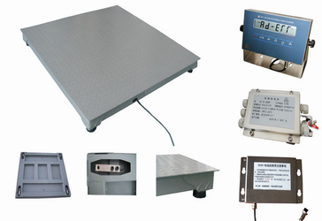
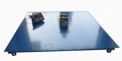
Third, through the junction box to adjust the electronic floor scale difference 1. In the balance platform flat, the basic balance of the sensor force on the basis of the angle adjustment.
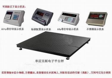
2. Partial load adjustment method The floor scale after new installation or replacement of sensors is generally subjected to angle adjustment. According to the fixed floor scale GB/T7723-2002, the load is applied to each supporting point in turn, occupying an area approximately equal to the load carrier. 1/N (N is the number of support points), the applied load is approximately equal to the sum of the maximum weight and the maximum added tare 1/N-1 (N is the number of fulcrums), and the measured offset error should not be greater than The maximum allowable error is 0.5e (500<m≤500 hours or 1.0e (500<m≤2000 hours).
The actual adjustment of the angle difference is: the load is concentrated on the top of the sensor being adjusted as much as possible. The larger the load, the more concentrated the placement, the easier it is to adjust. The method of adjustment is to load each sensor sequentially with the same weight and record the values ​​of each point, and then use the middle value as the criterion, turn the display high to low-key, and turn the display low to high to near the middle value. Adjust the sensor corresponding potentiometer, so that each corner shows the same.
IE2 Standard motor is totally enclosed and fan cooled 3 phase squirrel cage induction motor. It is newly designed in conformity with the relevant rules of IEC&DIN42673 standards.
Application:
IE2 Standard 3 phase motors are widely used as driving equipments of various machineries such as: machine tools, blowers, pumps, compressors, transporters, agricultural and food processing
Operating Condition:
Ambient temperature: -15°c to 40 °c
Altitude: ≤1000m
Rated voltage: 380V, 400V, 415V, 220V, 230V, 240V, etc
Rated frequency: 50HZ, 60HZ, 50HZ/60HZ
Duty: Continuous(S1)
Insulation class: Class B, Class F
Protection class: IP44, IP54, IP55
Cooling method: IC0141
Note:
The voltage and frequency could be made according to your request. If there is any requirements or inquiries, welcome to contact us.
IE2 Standard High Efficiency Three Phase Induction Motor
IE2 Induction Motor,Standard Induction Motor,High Efficiency Induction Motor,Three Phase Induction Motor
FUZHOU LANDTOP CO., LTD , https://www.landtopco.com