Insect lamp system software design A complete microcontroller-based trap lamp control system includes not only the hardware control part but also the software part. The hardware part of the solar insect killer lamp has built a platform for software work, and the software can make full use of the functions of the hardware, and can realize functions that some hardware circuits cannot achieve. So, in the control circuit of the one-chip computer, software and hardware complement each other, it is essential. The following is a discussion of the software implementation of the solar trap lamp controller.
1, the overall design of the system software
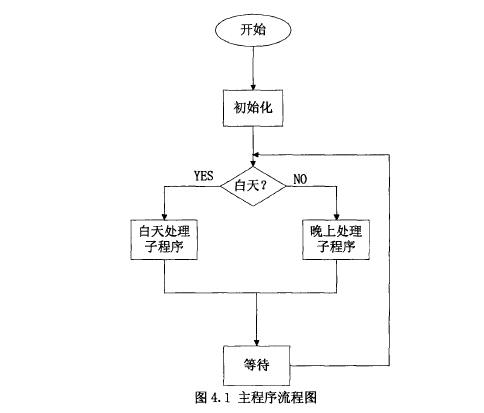
(l) The overall design of the system software When the microcontroller software is being compiled, the system is initialized first. Because the execution of some programs is based on interrupts, the interrupts should be closed before the initialization and the interrupts should be turned on after the initialization. According to the sampling voltage of the solar panel, it is judged whether it is daytime or nighttime. It is transferred to the daytime subroutine during the daytime, and is transferred to the evening subroutine at night. In the daytime subroutine, the voltage of the two terminals of the solar trap lamp is compared with the set voltage of the charging control, and four states of no charging, fast charging, PWM slow charging, and stopping charging are selected. Pæ» charge control subroutine to control the size of the charging voltage. And indicate the state of charge by the indicator light. The charging process will cause the battery temperature to rise, causing the battery charge conversion voltage will change, so need to set the temperature compensation subroutine. In the black-sky treatment program, the relay on the discharge circuit is sucked by software, and the terminal voltage of the solar trap lamp is compared with the discharge cut-off voltage to control the over-discharge switch.
(2) block diagram of the overall system software design (Figure 4.1)
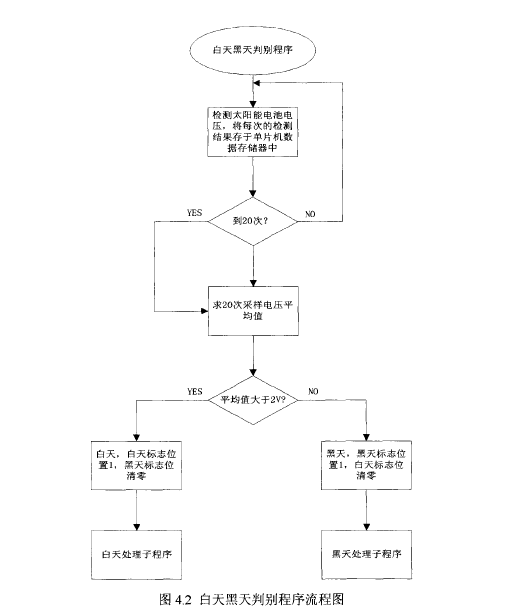
2, the identification of the day and night program design Solar induction lamp control system during daytime charging, black days control system discharge. When distinguishing between daytime and dark days, the voltage of the solar cell must first be detected and the solar panel voltage should be sampled. The sampling period is set to 105, and the sample is taken 20 times. The average of the 20 sample voltages is determined to be less than 2V (the solar panel is closed. Value voltage sample value). If less than 2V, it is dark; if it is more than 2V, it is daytime. At the same time, it will correspondingly reflect the position of the flag during the day or dark day. When it is determined as daytime, it is still necessary to judge whether the voltage of the solar panel is higher than the voltage of the battery, and the voltage of the solar panel cannot meet the charging requirements. When it is determined to be dark, turn on the inverter switch and turn on the load switch. At the same time, the voltage across the battery is detected and over-discharge is prevented by the switch tube control. Specific design flow chart shown in Figure 4,2:
3, daytime processing subroutine design Mainly to complete the battery charging during the day, the main process is as follows: Before the insect trap charge, first of all to detect whether the voltage of the solar panel can meet the charging requirements, in the detection of the battery voltage, because The battery terminal voltage state determines the form of charging. If the battery's terminal voltage is below 13.5V, it should make the charge control MOS always on, that is, take full power charging mode; if the battery terminal voltage is greater than 13.SV and less than 14.4V, adopt PWM control mode to charge; If the terminal voltage is greater than 14.4V, the charging circuit is turned off and the MOS transistor is turned off. In addition, during the charging process, it is also necessary to consider the influence of temperature and perform temperature compensation appropriately.
The flowchart of the specific daytime processing subroutine is shown in Figure 4.3:
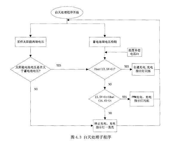
In Figure 4.3, the temperature compensation voltage is directly superimposed on the charge state transition voltage and the effect of temperature on the battery charge is eliminated as much as possible.
According to Fig. 4.3, when the battery terminal voltage Ubat of the trap lamp is less than 13.SV+Ut, the program makes the control port Pl.O output high, so that the MOS tube is always turned on, and charging is performed using the all-pass method. When the battery voltage is greater than 13.sv ten ut, less than 14.4v + ut, the battery is charged with PwM. As the charging process progresses, the battery's terminal voltage increases. At this time, the pulse width of the charging should be continuously narrowed. When the voltage of the battery rises to 14.4V+ut, the pulse width check bit is O, and the charging is stopped. . The PWM pulse width modulation charging method is implemented by software. The principle is shown in the figure below. When the battery terminal voltage Vbat=14.OSV, its charging PWM pulse width waveform is shown in Figure 4.4:
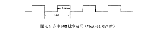
When the battery terminal voltage Vbat = 14.2v its charging PWM pulse width waveform shown in Figure 4.5:
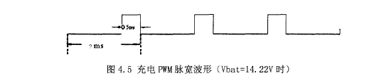
We take the period of the PWM pulse as ZMS, then the switching frequency of the MOS tube is SOOHz.
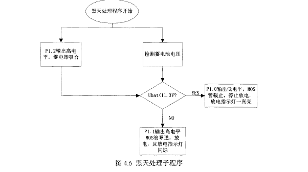
4, black day processing subroutine design solar energy trap lamp black day processing subroutine, mainly to control the discharge of the battery "the main process is as follows: by detecting the voltage of the solar panel to determine the black sky, into the black day processing subroutine" In this program, the discharge circuit in the discharge control circuit is mainly controlled. In the discharge circuit, after the black day is determined, the P1. 2 port determines the output high level, the relay pulls in, and then the discharge MOS tube is controlled according to the battery voltage. Open and close, when the battery voltage is less than H.3V, the MOS tube is closed, cut off the discharge loop, to prevent over-discharge. "Figure 4.6:
Related Instruments: Disease and Insect Investigator Disease Detector Special Software Spore Catcher
Standard:DIN2185
Material:C45
Contact Surface:>=85%
Model:MT
The Morse Taper Drill Sleeves are hardened steel, internally and externally ground. Size adaptors from one size stepping up to the next or skipping to a couple larger sizes (ie; 2- MT sleeve); this allows a No.2 Morse taper drill to be sleeved to suit a No.3 Morse taper machine spindle. Quite often several Drill Sleeves are joined together to gain the required Morse taper.
Morse tapers range from No.0 Morse taper up to No.7 Morse taper. No.3 is the most popular; drills aprox. 23mm thru to 32mm. Most bench drill presses are either No.2 or No.3 Morse taper spindles.
Morse taper sleeves are also available as an extension arbor whereby you can extend the length of a cutting tool using a 3MT - 3MT extension sleeve (aprox. 200mm in length).
MT Drill Sleeves
MT Drill Sleeves,Drill Sleeves for MT,Morse Taper Drill Sleeve,MT Drill Sleeves Size
SISHUI TELI TOOL CO.,LTD. , http://www.er-collets.com