Temperature rise test model construction is very important for the evaluation of electronic product performance. The temperature rise curve not only helps engineers verify the reliability and rationality of product design, but also more comprehensively evaluates the overall performance of the product. So how can we get an accurate temperature rise curve?
First, temperature rise test
To verify the lifespan and stability of electronic products, the temperature rise of their important components (IC chip, IGBT, etc.) is usually tested, and the device under test is placed at a specific temperature (such as room temperature or a certain temperature). After operation, the temperature rise of the components above the ambient temperature is recorded after stabilization, and the reliability of the product and the rationality of the product design are verified by determining whether the temperature rise of each component of the product meets the allowable value of the standard.
The purpose of temperature rise is to collect the temperature change status of each test point: Observe whether the change of temperature curve is reasonable, such as whether the temperature rise is within the allowable range; if there is any abnormality, stop the test, save the existing data, and view and analyze the reason. Figure 1 shows the temperature rise record.

Figure 1 Temperature rise curve
So how does the temperature rise record and calculate it?
1, the traditional test method:
After the working temperature of the measured object is collected by ordinary data mining, EXCEL is manually used to do a large amount of data calculation, and the working temperature of the measured object is a fixed room temperature value; however, the traditional method requires a lot of labor costs and the test result is inaccurate.
2, new data mining test methods:
The difference between the input (working temperature of the measured object) and the measured value of the reference channel (test environment temperature, such as room temperature) is taken as the measured value of the channel by the Delta operation method. In the temperature measurement, the difference between the room temperature and the room temperature is easily measured. As shown in Figure 2.
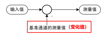
Figure 2 Operational model
Second, the test environment to build
For example, in the room temperature 25 °C environment, do the temperature rise test, that is, on the surface of all key components, such as IGBT, inductors and other semiconductor devices or magnetic devices, usually use thermocouples (R, S, B, K, E, J, T, N type) wiring.
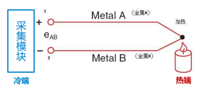
Figure 3 Test method
Thermocouple solder joint: Place the thermocouple probe on the measured position and apply glue;
Thermocouple wiring: The wires inside the machine should be as tidy as possible, and they should be tied with high-temperature adhesive tape, and go troughs or wire troughs;
Thermocouple outlet: Do not lead from the air inlet or outlet or other unsafe places.
When there are two different conductors or semi-conductors A and B that form a loop and their two ends are connected to each other, as long as the temperature at the two junctions is different, the temperature at one end is T, which is called working end or hot end, and the other end is at temperature T0 Called the free end (also called the reference end) or the cold end, an electromotive force is generated in the loop. The direction and size of the electromotive force are related to the material of the conductor and the temperature of the two contacts. This phenomenon is called "thermoelectric effect", and the circuit composed of two conductors is called "thermocouple". These two kinds of conductors are called "hot electrodes", and the generated electromotive force is called "thermal electromotive force." The temperature rise process is determined by this model.
Third, multi-level cascaded distributed acquisition
When the measurement site is relatively decentralized, the measurement site and the data logger can be installed separately to avoid long-distance connection of signal lines. With multiple cascades, the DM100 data acquisition recorder can be expanded to a maximum of 200 acquisition channels, which is highly scalable and suitable for multi-channel data acquisition and recording. Figure 4 shows the cascade mode.

Figure 4 Cascade mode
Fourth, the data summary operation
Analog signal acquisition module uses 32-bit ADC sampling, DC voltage accuracy of up to 0.05%, modules can be synchronized sampling, the fastest sampling period 100ms/10 points. Isolation voltage between channels is 1000V AC, effectively shielding the interference between channels. The built-in digital filter can effectively eliminate the power frequency and high frequency noise interference, adapt to the changes of the on-site environment, and stably work in the industrial environment, so as to obtain accurate original calculation data. Figure 5 shows the data exported by the Web form.
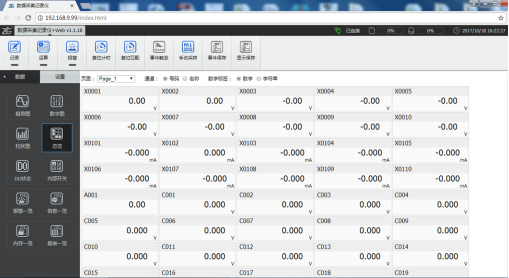
Figure 5 Web data.
Zhiyuan Electronics DM100 and DP100 data acquisition recorders are general-purpose data acquisition devices. Through a modular design framework, they provide users with diverse data acquisition modules to fully collect DC voltage, DC current, digital quantities, temperature, humidity, etc. A variety of sensor signal data can be manipulated in real time and display a variety of measurement results. The user can perform custom calculations on the collected data and achieve highly reliable data storage and recording functions. The DM100 and DP100 data acquisition recorders provide users with a convenient and reliable data acquisition instrument from data acquisition, measurement operations, and storage records.
Heavy Fork,Forge Fork,Forging Forklift Forks,Heavy Forged Forklift Forks
Shandong Techence Forging Co.,Ltd , https://www.shandongtechence.com