Finite Element Analysis and System Design of Forklift Gantry

Baoji Heli Forklift Factory – Wu Jinggang, Zhang Zhancang
Chang’an University – Ma Pengfei
[Abstract]: This paper presents a finite element analysis approach to evaluate the structural behavior of a forklift gantry. By simplifying the gantry model and developing dedicated software for finite element calculations, this study provides a practical method for analyzing and designing forklift frames. The methodology can also serve as a reference for similar engineering structures, offering an efficient and accurate way to assess load distribution and structural integrity.
[Keywords]: Finite element analysis, forklift gantry, structural design, software development, engineering simulation. The finite element method is widely applied in engineering fields as a powerful tool for scientific research and structural analysis. Traditional forklift frame design often focuses only on major stress points, lacking comprehensive evaluation of the entire structure. By implementing finite element analysis, this study aims to offer a more intuitive and user-friendly environment for engineers to understand the stress distribution and optimize the design of forklift frames.
1. Calculation Model of Forklift Frame Structure
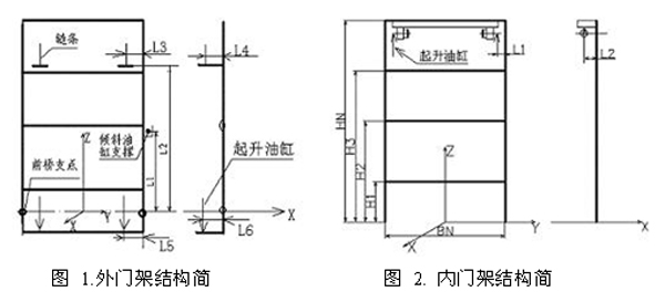
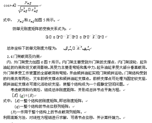
The connection between the inner and outer gantry of a forklift is achieved through rollers embedded in channel steel. The number of beams varies depending on the maximum lifting height, with a minimum of 2 and a maximum of 4 inner beams, while the outer girders can have up to 5 and as few as 4. When lifting, the hoist lifts the inner gantry, which in turn raises the forks. The outer gantry swings using a tilt cylinder, with the front axle acting as the pivot point, allowing a total swing range of 12 degrees.
For easier calculation and analysis, the gantry structure is simplified. Figures 1 and 2 illustrate the inner and outer gantry’s structure and dimensions. Considering the movement and loading conditions, both inner and outer girders are analyzed using space beam elements in the finite element method.
2. Stiffness Matrix and Coordinate Transformation
2.1 Unit Node Displacement and Node Force
For a space beam element, the node displacements and forces are illustrated in Figure 3. The displacement matrix at node i is given by:

Similarly, the displacement matrix at node j is:

The combined displacement matrix for the unit is:

The force matrices at nodes i and j are expressed as:

J-node force matrix:

Unit node force matrix:

2.2 Element Stiffness Matrix
The element stiffness equation is given by:

Where  represents the element stiffness matrix, and
  is the rod end displacement.
The stiffness matrix in the above equation can be divided into four sub-matrices, resulting in a 12×12 matrix due to the 12 degrees of freedom in a space beam element.

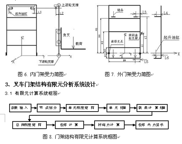
The overall process includes meshing the structure into beam elements, applying loads, calculating the element stiffness matrix, assembling the global stiffness matrix, solving for displacements, and determining internal forces. The program is developed using Visual Basic (VB), allowing users to directly view results such as displacement, stress, and internal forces.
4. Finite Element Calculation Software System Design
The system consists of three main components: parameter input, node division, and result display. Parameter input includes load, structural, and material properties. Channel steel is used for columns, and A3 steel for beams with rectangular cross-sections. The material database stores relevant parameters, and users only need to select the appropriate channel steel model and input the beam's dimensions.
The background processing involves mesh generation and finite element calculations, while the interface remains simple. The core functionality lies in the underlying program that performs the actual computations. Results can be displayed in two ways: graphical representation using Picturebox control for internal force diagrams, and data output via RichTextBox controls by reading generated text files. An example of the outer frame bending moment diagram is shown in Figure 12.
5. Conclusion
Through the analysis of the forklift frame, a computational model was established, and coordinate transformation under spatial coordinates was addressed. Based on this, a finite element calculation and analysis software system was developed, providing an effective method for evaluating and optimizing forklift gantry structures.
[References]
[1] Liu Jiqing, "Structural Mechanics", National Defense Industry Press, April 1985, Beijing.
[2] Lei Xiaoyan, "Finite Element Method", China Railway Publishing House, October 2000.
[3] Liu Erlie, "Finite Element Method and Programming", Tianjin University Press, July 1999.
[4] Qingyuan Computer Studio, "Visual Basic 6.0 Development Handbook", Machinery Industry Press, April 1999.
Carpet Film,Pe Plastic Masking Film,Scratch Protection Film,Transparent Protection Film
Wuxi Xinhao Protective Film CO.,Ltd , https://www.cotton-balewrap.com